INFORMATION and LICENCE
Tues Design Co. ‘CARD’ Business Card / Bluetooth Game Controller
ID 0002, Mark 1 A ‘ALBEDO’
Designed By Constantine Lucius Pallas (2024-2025)
TUES DESIGN CARD HARDWARE SCHEMATICS, PRODUCTION FILES, FIRMWARE CONFIGURATION, DOCUMENTATION and RELATED MATERIALS are provided AS IS under the CERN OHL v2 Strongly Reciprocal license.
BUILD GUIDE
Hi there. I’m Constantine, and if you’re reading this page, you likely acquired one of my business cards, and you’re interested in turning it into a game controller. This document should give you everything you need to complete your build.
Parts List
- 1x TUES DESIGN CARD mainboard (the business card)
- 11x Kailh Choc Mechanical Keyboard Switches (Not Cherry MX switches)
- 11x Kailh Choc Hot-Swap Sockets (Not Cherry MX sockets)
- 11x Square Choc Keycaps (16.5x16.5mm) - I used these (Not Cherry MX keycaps)
- 1x Seeed Studio XIAO nRF52840 Sense (you may be able to use a different microcontroller with the same pinout and footprint, but I cannot guarantee compatibility)
- The standard Seeed Studio XIAO nRF52840 has the same pinout, footprint, and even bluetooth features, so it’s probably the next best thing (I haven’t tried it myself though).
- If you have had success with an alternate microcontroller, please email me and I’ll amend the list.
- (Optional, advanced) 1x Compatible Battery and connectors - This is required for Bluetooth support and wireless capabilities.
Required Tools and Materials
- Soldering Iron (I recommend using a small tip)
- Solder Paste (it is possible to use solder wire, but it is far easier with paste)
- USB-C cable (required to flash the ZMK firmware)
- Computer (required to flash the ZMK firmware)
- 3D Printer and Filament/Resin (required to fabricate the optional but highly recommended case. If you do not have a 3D printer, I suggest using a 3D printing service, or visiting a local makerspace)
Step 1: Soldering
First, Solder the XIAO Microcontroller to the designated place on the back of the mainboard. An outline is provided for easy alignment.
If you are planning on adding a battery, ensure that the BAT+ and BAT- pads on the XIAO are soldered to the mainboard before proceeding to solder the side pads. Be very careful not to short these pads, as doing so could be a fire risk. If you have a V1 version of the card (Indicated by 3 rectangular copper pads next to the L2 button on the back of the board), it can be somewhat challenging to get good contact between the battery pads on the XIAO and the pads on the board.
Soldering the side pads is quite simple. The ENIG finish on the mainboard and the castellated pads on the XIAO ensures plenty of solder paste can adhere the surfaces. You can use male header pins to make the process even easier, but you may have to clip the ends to fit the board in the case.
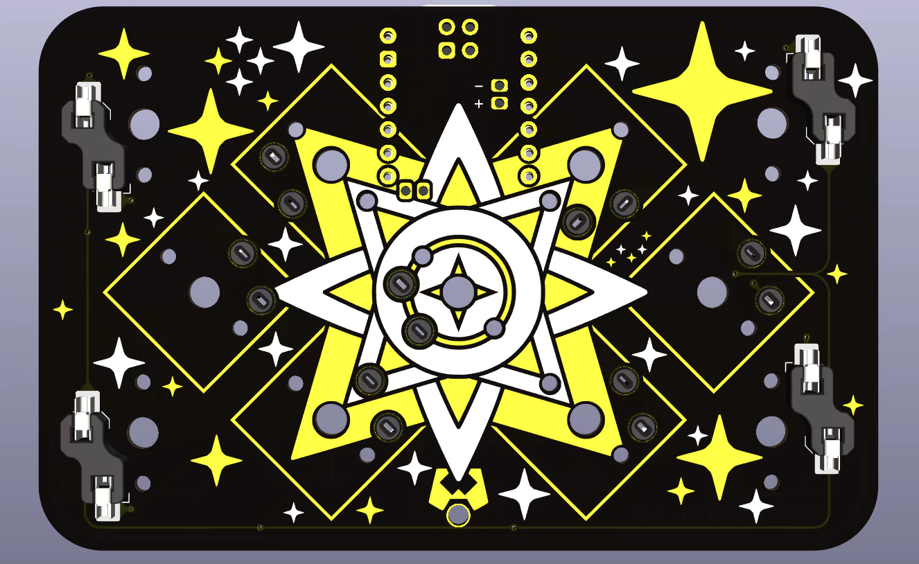
Next, Solder the 11 Hot-Swap Sockets must be soldered to the board. Four are affixed to the front (for the back buttons) and seven are affixed to the back (for the front buttons). There is an outline printed on the correct side of the board to align each socket. These renders illustrate how each part should be affixed.
Back:
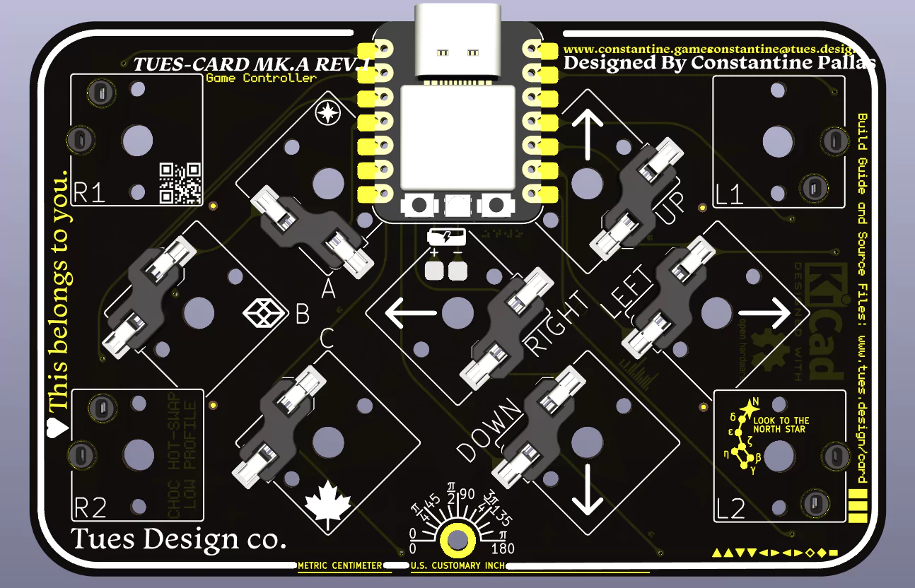 Front:
Step 2: Case and Assembly
If you are unsure if you soldered everything correctly, you can insert the switches (taking note of the rotation of each switch), skip ahead to Step 3, and return to this step after verifying the
First, print a case. My good friend Daniel Fiuk created a simple case designed for wired use. If you’d like to use wireless, You will likely also require an interior volume for the battery. As the controller is not designed for use with a specific battery, I would suggest using Blender to modify this design to add space for yours. You can also create your own design, making use of the STEP files available on the PCB GitHub page.
A revised official case is in the works. The new case will have improved ergonomics, support for a battery pack, and greater strength. This guide will be updated with a link to download the free, open source 3D print files for the new case when it is ready. You should have no problems esily switching cases.
 When 3D printing this case using an FDM printer, I would suggest aligning each ‘flat’ side to the build plate (the outside of the top half and the inside of the back half).
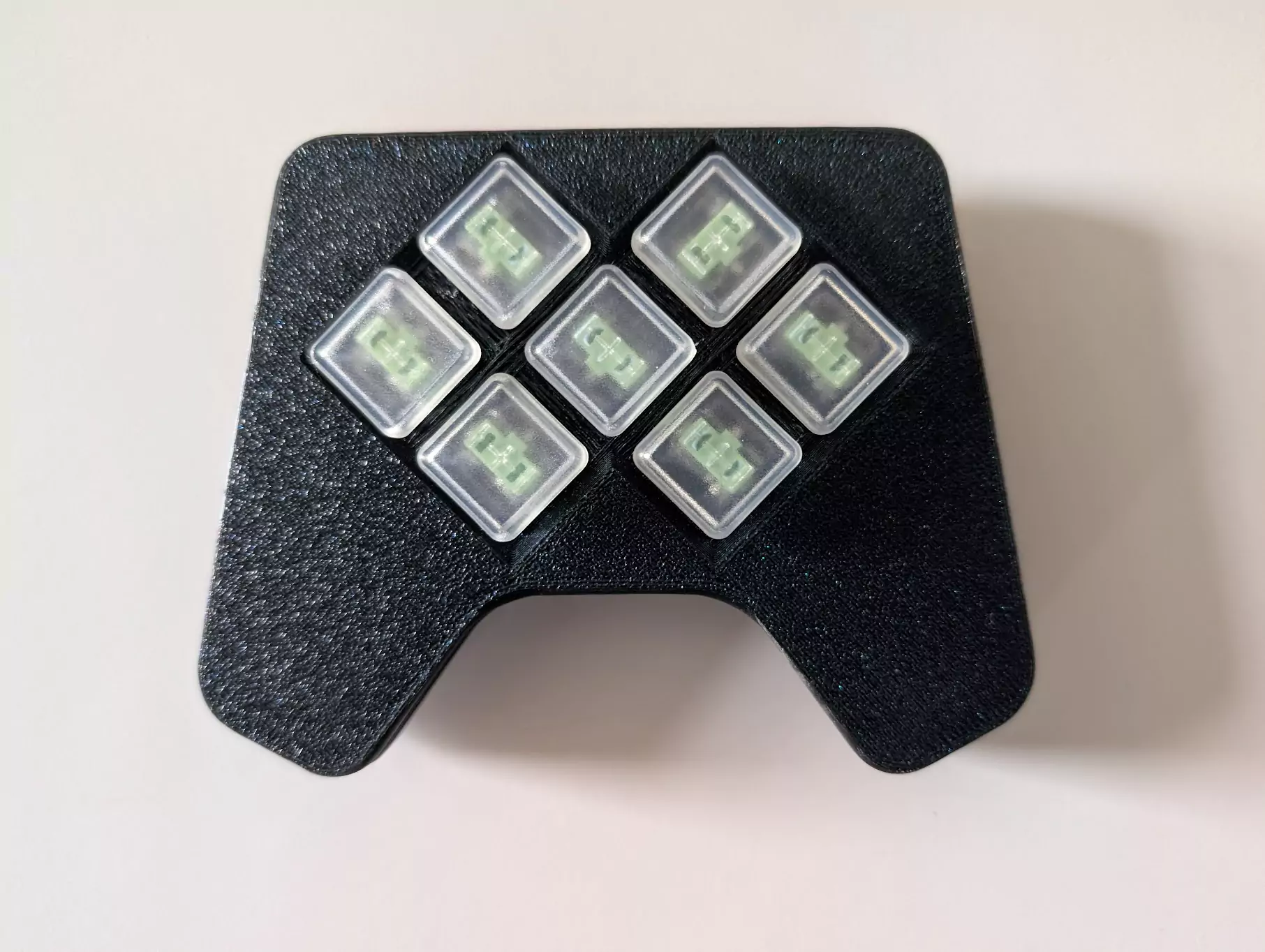
Assembly is very simple. Sandwich the PCB with parts soldered between the halves of the case. The case is held together using the ‘Plate Mount’ method, meaning that the case sits between the PCB and the switches, and friction holds everything together. You should be able to insert the switches into the assembly now, taking note of the rotation of each switch. The only remaining step is to attach the keycaps to the switches. If your keycaps are not square, they may not look perfectly aligned, so I’d recommend using square ones such as those offered by ChosFox.
Step 3: Firmware
Now that you’ve built your controller, you’re ready to start using it with games. Download the Firmware File (extract the zip, you want the UF2 file). To flash the firmware to the board, plug the controller into your computer. The exact method might vary, but on the nRF52840 Sense, quickly press the reset button twice. The reset button is a small button next to the USB port. You will know this worked when a new drive appears in your File Explorer/Finder. All you have to do to flash the firmware is to drag or paste the firmware.uf2 file into this drive. It’ll disappear and the controller should now work.
Step 4: Usage and Remapping
Now that the firmware has been flashed, the buttons should be mapped to their default keys. This might not be ideal for your application (perhaps the game you’re playing doesn’t have remappable controls, or you would like to use chording/layers to add additional functionality). You can easily remap the hardware using ZMK Studio (the bottom right key on the back is set to ‘unlock’ this program by default).
Notes
Thanks for reading! If you have any questions feel free to reach out to constantine@tues.design. I plan to update this page with a video build guide and additional resources.